When a rough surface is irradiated by coherent light like Laser, a speckle pattern can be seen. Fig. 1 is an example.
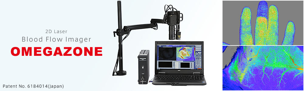
The speckle pattern is the result of the summation of scattered light from many points. It is caused by that the scatted lightsfrom many points have different phase each other. When non-moving particles are irradiated, the speckle pattern does not temporally change because the relation between the phases of the lights is constant. Therefore, the light intensity does not temporally change.However, when moving particles areirradiated, the speckle pattern changes. The speed of this change of the pattern depends on the velocity of the moving particles. Therefore, it is possible to know the velocity of the moving particles by measuring the temporal or spatial change of the speckle pattern intensity. This principle is used for the Laser Speckle Blood Flow Imager, OMEGAZONE. The laser light reaches under skin or inside of tissue, and the moving particles are erythrocytes(RBCs) in the case of measuring living tissue.
Theory
Theory of Laser Speckle Blood Flow Imager
Origin of speckle pattern by Laser

Fig.1. Speckle pattern by laser light
When the laser light is irradiated on a tissue having a non-moving RBC(Fig.2), the electric field, E, detected by the photo detector is the summation of the scattered lights from many points.The scattered light from the static tissue and a RBC are not shifted in frequency. Therefore,the relation between the each phase of the scattered lights is temporally and spatially constant, and the signal of the light intensity, I, from the photo detector is constant, too. The intensity, I, is expressed as I ∝┃E┃2.
The case a RBC is moving in a tissue is considered next.
Fig.2. Summation of scattered lights from non-moving RBC and static tissue
When the RBC moves from the time t1 to t2 in the velocity(Fig.3), V, in the tissue, the scattered light is shifted in frequency. However, the scattered light from the static tissue is not shifted in frequency, and its phase does not temporally change on the photo detector. Then, there is the discrepancy of the two phases on the photo detector. Also, when the RBC moves continuously, this discrepancy temporally changes. Therefore, the electric field, E, fluctuates by the summation of the scattered lights from many points, and the light intensity of the photo detector fluctuates, too. The speed and the magnitude of the fluctuation are related to the velocity and the number density of RBCs respectively.
The simple theoretical equations are described below.
The vector of the laser light irradiated on a moving RBC is represented asKf、and the wave vector of the scattered light is represented as Ki. Here, Ki= (2πλ)・u and u is the unit vector. The electric field of the scattered light is expressed as
E=Eoexp[-i(Kf–Ki)・vt]
Here, Eois the electric field of the light irradiated on the moving RBC, and v is the vector of the velocity.
This equation shows that the phase component being in proportion to the velocity of the RBC is added on the original laser light. Also, the frequency shift, Δω, can be expressed as
Δω = (Kf–Ki)・v
The laser tissue blood flowmeter using a fiber optic probe is treated as that the scattered lights from RBCs are Doppler shifted, but the instrument does not measure the Doppler shifted frequency itself. The detected light of the photo detector shows temporal fluctuation in the optical intensity, and tissue blood flow value is calculated from the intensity and the component of the fluctuation of the detected light.
Refer the following book for the dynamic light scattering.
B. J. Berne and R. Pecora : Dynamic Light Scattering, Wiley, New York(1976).
Fig.3. Summation of scattered lights from moving RBC and static tissue
Signal processing
The laser blood flowmeter using a fiber optic probe can detect the scattered light through the optical fiber, and calculate blood flow value continuously because it uses one photo detector (photo-diode). However, it is needed to detect many points at the same time and continuously for 2D measurement. The OMEGAZONE uses a CCD camera, and the fluctuation in every pixel in a certain time is used to calculate blood flow value of each pixel.
The output of a pixel (light intensity) is constant when a non-moving particle is irradiated by laser light (Fig.4).
Fig.4. Intensity of a pixel when a non-moving particle is irradiated.
However, when a moving particle is measured the detected light intensity fluctuates as expressed in the previous section (Fig.5).
Fig.5. Intensity of a pixel when a moving particle is irradiated.
The electric charge of a CCD pixel is gradually integrated in the accumulation time. Therefore, the integrated electric charge is not constant in the accumulation time like Fig.5, but the figure shows the averaged intensity to make it plain.
a) In the case of faster velocity of RBCs :When the velocity of moving RBCs becomes faster, the detected light intensity fluctuates faster and then the deviation of the averaged electric charge of the CCD pixel becomes smaller (Fig.6).
Fig.6. Intensity of a pixel when RBC velocity is fast.
b) In the case of higher number density of RBCs :When the number density of RBCs in tissue, many scattered light from the RBCs are summed and then the deviation of the averaged electric charge of the CCD pixel becomes smaller (Fig.7).
This phenomenon is used to obtain the tissue blood flow value. The scattered lightsfrom tissue are detected by the pixels of a CCD camera in a certain time (1/60 sec, or 1/30 sec), and the tissue blood flow value is calculated from the deviation of the outputs of the pixels as σ/. These figures are explained by the temporal mode, but the spatial mode has the same phenomenon and can be used to obtain tissue blood flow value.
The fiber optic laser blood flowmeter shows higher blood flow value when the fluctuation of the detected light intensity is faster or bigger, but the 2D speckle blood flow imager shows higher blood flow value when the deviation of the detected light intensity is smaller. The relation between the fiber optic laser blood flowmetry and the speckle blood flow imaging theory is reported by Briers, and it shows that the two instruments are fundamentally the same.
Fig.7. .Intensity of a pixel when RBC number density is high.
Briers, J. D.: Laser Doppler and Time-varying Speckle: A Reconciliation, Opt. Soc. Am. A, 13, 345-350 (1996).
Operation mode of OMEGAZONE
The basic software of OMEGAZONE was developed by Dr. K. Forrester in the University of Calgary.
OMEGAZONE has three modes of tissue blood flow measurement.
High resolution mode (HR)
This mode shows about 2 blood flow images/second in high resolution (638×480).
This is the temporal mode expressed in [2] Signal processing] and one blood flow image is calculated from sequential 20 real images.
The blood flow signal of the pixel on the point of (x,y) is expressed as the next equation.
Here, Ac is the constant of C, and はC is a multiplier.
ISD is the standard deviation of the light intensity (electric charge) of the pixel at (x,y) and it is normalized by the average light intensity calculated from the sequential 20 images.
High speed mode (HS)
This mode shows about 15 blood flow images/second in low resolution.
This is the spatial mode and one blood flow image is calculated from one real image. The average light intensity and the standard deviation are obtained from the 3×3 pixels, and the blood flow value is shows as the average of 9 pixels. Therefore, the resolution becomes 1/9 of the HR mode, 212×160.
High speed average mode (HS-AVG)
This mode is the averaged HS mode. The number of averaging can be specified. This mode shows smooth blood flow image by the averaging.
Exponential moving average mode (EMA)
This mode shows over 30 blood flow images/ second. The resolution is the same as HR mode (638×480).
The blood flow image of HR mode is calculated from 20 real images, but this mode calculates one blood flow image by the continuous exponential moving average. This mode can show human pulsatile flow.
Refer the next paper for the details.
Forrester, K. R., Stewart, C., Tulip, J., Leonard, C. and Bray, R. C. : Comparison of Laser Speckle and Laser Doppler Perfusion Imaging : Measurement in Human Skin and Rabbit Articular Tissue, Med. Biolog. Eng.& Comp., 40, 687-697 (2002).
When the standard deviation of the detected light in a pixel becomes smaller, the calculated blood flow value higher in the theory. The HR mode and EMA mode are calculated from the summation of the detected light intensity on the same pixel. When a rigid material like a plastic board is measured, the sequential detected light intensity on one pixel is almost constant. Therefore, the standard deviation is very small, and then it shows higher blood flow value.
In the case of measuring a non-moving material, use the HS or HAS mode. These spatial modes calculate the standard deviation from 9 pixels, and these modes do not show high blood flow value.
Tissue slightly moves after the living body died. Therefor the HR and EMA mode shows low blood flow and the modes can measure the blood flow after dying.
Measurement depth
The incident point and receiving point are separated, and the distribution of the light intensity in a tissue is the function of the distance for the fiber optic laser blood flowmeter. Therefore, the relative measurement depth depends on the distance between the incidence point and receiving point. However, the laser light is irradiated on a wide area and pixels detect the scattered light from the same points as the irradiated points for the 2D laser speckle blood flow imager. It is equivalent to that the incidence point and receiving point are on the same point for the fiber optic laser blood flowmeter, and the measurement depth becomes shallower. It is assumed that the measurement depth for human skin is about 1 mm or less from the surface. Refer the following paper.
Kashima, S., Spectroscopic Measurement of Blood Volume and Its Oxygenation in a Small Volume of Tissue using Red Laser Lights and Differential Calculation between two Point Detections, Opt $ Laser Technol.,35, 485-489 (2003).
Surface reflection and polarization
OMEGAZONE uses the effect of polarization. The laser light used in OMEGAZONE has a linear polarization, and the reflected light from tissue surface has the same direction of polarization. The intensity of this reflected light is not constant, and it causes the noise in the measurement and calculates lower blood flow value.
The hybrid filter of the polarizer and optical band-pass filter is attached to the lens for OMREGAZONE. The direction of the polarization of this filter is set to perpendicular to that of the laser light not to detect the reflected light from the surface of tissue.
Refer the following paper.
S. Kashima : Non-contact Laser Tissue Blood Flow Measurement using Polarization to Reduce the Specular Reflection Artifact, Optics & Laser technol., 26, 169 (1993).
Unit of tissue blood flow and the characteristic of Laser Blood Flowmetry
The unit of tissue blood flow is generally expressed as [mL/min/100g] in medical field. It means that blood flows, mL, into a unit tissue of 100g in a unit time, min. This unit is based on the measurement of liquid, but the Laser Blood Flowmetry (LBF ) does not detect blood flow as the liquid, but as the scattered light from RBCs. Then it is not right to express in the unit for liquid. The exact unit of tissue blood flow measured by LBF is like [N/mm3]×[mm/s]] 1). It means the multiplication of the number density of RBCs in a tissue by the mean velocity. However, this kind of unit is not familiar to medical doctors and they do not know if the measurement value expressed in this unit is rich flow or not. Therefore, our LBFs show the blood flow values being equivalent to the values in [mL/min/100g] 2).
LBF detects the number density of RBC and the velocity, LBF shows different value (FLOW) even if the blood flows in a tissue in a unit time is same. Figure. 8 and 9 have the different vascular structures in the detected volume of tissue by LBF. As an example, the length of the blood vessel in Fig. 9 is B times of that in Fig. 8, and the both of diameter are the same. When the blood flow of “a” [mL/min] flows into the tissue and when it is converted into 100 g, the “tissue blood flow” value as the concept will be expressed as A [mL/min/100g] for the both of tissues. It is because the tissue blood flow unit does not take account of the blood vessel construction in tissue under study. However, the LBF detects the number density and velocity of RBCs. Therefore, when LBF shows the value of “A” for Fig. 8, the value for Fig. 9 will be “A・B” because the number density is B times, and the velocity is the same as that in Fig. 8.
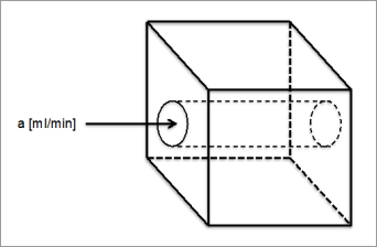
Fig.8. Straight blood vessel
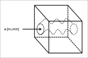
Fig.9. Winding blood vessel Length is B times of Fig. 8.
1) S. Kashima : Study of Measuring the Velocity of Erythrocytes in Tissue by the Dynamic Light Scattering Method, Jpn. J. Appl. Phys., 32, 2177 (1993).
2) S. Kashima : Measurement of Tissue Blood Volume in a Model System and in the Canine Intestine by Dynamic Light Scattering, Laser. Life Sci., 6, 79 (1994).
Laser Speckle Tissue Blood Flow Imager OMEGAZONE Summary / Spec | Theory | Price List

OMEGAWAVE, INC.
2-20-3 Katamachi, Fuchu, Tokyo Japan
TEL 042-352-1171