Fiber Optic Laser Blood Flowmeter OMEGAFLO

Theory and Measurement example

Theory

The laser tissue (Doppler) blood flowmeter (LBF) measures tissue blood flow based on the fluctuation of the scattered laser light from tissue. This LBF is for tissue blood flow including microcirculations, but not for one blood vessel.
The laser light is scattered by static tissue and change the direction before colliding red blood cells (RBC), and the blood flow direction in microcirculation is not unit. Therefore, the information of the blood flow velocity is proportional to RMS.

When the laser light is irradiated on a tissue having a non-moving RBC (Fig.1), the electric field, E, detected by the photo detector is the summation of the scattered lights from many points. The scattered light from the static tissue and a RBC are not shifted in frequency. Therefore, the relation between the each phase of the scattered lights is temporally and spatially constant, and the signal of the light intensity, I, from the photo detector is constant, too. The intensity, I, is expressed as I ∝┃E┃2.

The case a RBC is moving in a tissue is considered next.

Fig.1 Scattered light from non-moving particles and static material

Fig.1 Scattered light from non-moving particles and static material

When the RBC moves from the time t1 to t2 in the velocity (Fig. 2), V, in the tissue, the scattered light is shifted in frequency. However, the scattered light from the static tissue is not shifted in frequency, and its phase does not temporally change on the photo detector. Then, there is the discrepancy of the two phases on the photo detector. Also, when the RBC moves continuously, this discrepancy temporally changes. Therefore, the electric field, E, fluctuates by the summation of the scattered lights from many points, and the light intensity of the photo detector fluctuates, too (Ki andKf : wave vectors) .
The speed and the magnitude of the fluctuation are related to the velocity and the number density of RBCs respectively.
The simple theoretical equations are described below.
The vector of the laser light irradiated on a moving RBC is represented asKf、and the wave vector of the scattered light is represented as Ki. Here, Ki= (2πλ)・u and u is the unit vector. The electric field of the scattered light is expressed as
E = Eoexp[-i(Kf – Ki)・vt].
Here, Eois the electric field of the light irradiated on the moving RBC, and v is the vector of the velocity.
This equation shows that the phase component being in proportion to the velocity of the RBC is added on the original laser light. Also, the frequency shift, Δω, can be expressed as
Δω = (Kf – Ki)・v.
The laser tissue blood flowmeter using a fiber optic probe is treated as that the scattered lights from RBCs are Doppler shifted, but the instrument does not measure the Doppler shifted frequency itself. The detected light of the photo detector shows temporal fluctuation in the optical intensity, and tissue blood flow value is calculated from the intensity and the component of the fluctuation of the detected light as the normalized first moment of the power spectrum,
FLOW = ∫ωP(ω)dω(1).
Here, ω is angular frequency and P(ω) is the power spectrum of the detected light intensity.
The blood volume (Density of RBCs ), VOLUME(MASS)、is calculated by integrating the power spectrum as eq. (2).
VOLUME∝ [-ln{1-k∫P(ω)}](2)
Also, blood flow velocity, VELOCITY, is proportional to the mean angular frequency, <ω>, and it is calculated as eq.(3).
VELOCITY ∝<ω>≒ [2π2/(3αλ2)]1/2[1+0.27m](3)

Fig.2 Scattered light from moving particles and static material

Fig.2 Scattered light from moving particles and static material

Here, V is the velocity of RBCs, αis the distribution of the scattered light in the wave-lengthλ, and m is the average collision number of photons by RBCs. The mean frequency of the power spectrum is about 1[KHz] when the mean velocity of RBCs is 3 mm/s in the case of 780 nm laser light.1)

The laser diode having 780 nm wavelength is used for measurement because the difference of the absorption between Oxy-Hb and Deoxy-Hb is small. The optical fibers in a probe are graded index fibers and the core diameter is 100 µm. The distance between the incidence and receiving of the standard contact type probe is 0.5 mm, and the measurement depth is about 1 mm from the surface.
Figure 3 shows the block diagram of the conventional LBF, FLO-C1.

Fig3. Block diagram of Laser tblood flowmeter

Fig.3 Block diagram of Laser tblood flowmeter

Example of Measurement

Figure 4 shows the measurement example of a finger skin by FLO-C1.
The pulsatile flow is shown in FLOW. When the upper arm was occluded by 200 mmHg, FLOW and VELOCITY decreased rapidly, but VOLUME(MASS) did not show the decrease. It is because that the blood was washed away to fingers by the occlusion, and the blood remained there during the occlusion.

Fig.4. Example of measurement

Fig.4 Example of measurement

Measurement depth

The measurement depth of LBF is a function of the distance between the incident point and receiving point. The detected laser light intensity, Id, is expressed as,

  Id = η・Io・exp ( -γ・L ),

When the tissue is highly scattering material and the Beer-Lambert law is applied.
Here,
η : the coefficient depended on the optical system,
Io : the incident laser light intensity,
γ : the attenuation coefficient of the tissue, and
L : the length the laser light passes.
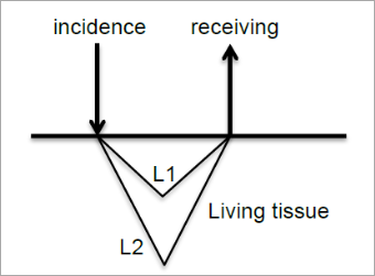
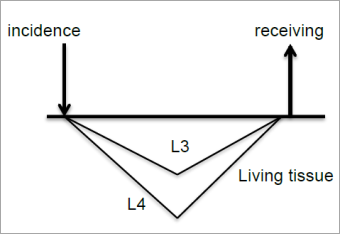
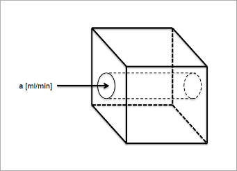
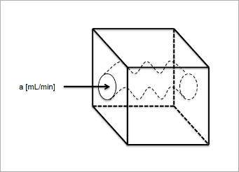
When the distance between the incidence and receiving point becomes longer, the total detected light intensity becomes weaker, but the measurement depth becomes deeper. The reason is that the difference of the detected light intensity between from shallow part and from deeper part becomes smaller when the distance becomes longer. Fig.5 and 6 show the state. Fig. 5 is for the distance is short, and Fig. 6 is for long.
The passage lengths of the light returned from the same depth in the two figures are L1 and L3, and L2 and L4. The light intensity passed through L1 is much stronger than that through L2 because L2 >> L1 in Fig. 5. Therefore, the ratio of the light intensity through L1 is dominant in the total detected light intensity. However, L3 is not so short compared with L4 in Fig.6, therefore, the ratio of the light intensity through L4 relatively becomes lager in the total detected light intensity.

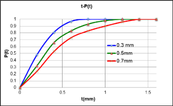
The graph, Fig. 7 shows the result of a model experiment by using polyacetal sheets. The polyacetal sheet has almost the same optical characteristic as human skin1). The distance between the incident and receiving points was set as 0.3, 0.5 and 0.7 mm, and the detected light intensity was measured by piling the 0.2 mm polyacetal sheets. The X-axis is the thickness, t, of the piled sheets, and the Y-axis is the cumulative probability, P(t), normalized by the maximum intensity. This characteristic depends on the divergence of the incident light and the receiving device. In this case, 100 µm optical fibers were used for the incidence and receiving.

This graph shows that the longer distance between the incidence and receiving includes the blood flow signal from deeper part more. Also, it is not easy to decide the maximum measurement depth, like OO mm. For example, when the distance between the incidence and receiving is 0.5 mm, the blood flow signal to 0.8 mm depth occupies 90 % of the total blood flow measurement and, furthermore, the blood flow signal to about 1 mm depth can be detected. The regression analysis indicates that the measurement depth which occupies 95 % of the total blood flow signal is 1.55 X d + 0.12, R2 = 0.999. Here, d is the distance between the incidence and receiving.


Fig. 5

Fig. 5 Short distance


Fig. 6

Fig. 6 Long distance


Fig.7

Fig. 7 Relationship between the incidence-receiving distance and measurement depth


Unit of tissue blood flow and the characteristic of LBF

The unit of tissue blood flow is generally expressed as [mL/min/100g] in medical field. It means that blood flows, mL, into a unit tissue of 100g in a unit time, min. This unit is based on the measurement of liquid, but LBF does not detect blood flow as the liquid, but as the scattered light from RBCs. Then it is not right to express in the unit for liquid. The exact unit of tissue blood flow measured by LBF is like [N/mm3]×[mm/s]] 2).It means the multiplication of the number density of RBCs in a tissue by the mean velocity. However, this kind of unit is not familiar to medical doctors and they do not know if the measurement value expressed in this unit is rich flow or not. Therefore, our LBFs show the blood flow values being equivalent to the values in [mL/min/100g] 3).
LBF detects the number density of RBC and the velocity, LBF shows different value (FLOW) even if the blood flows in a tissue in a unit time is same. Figure. 5 and 6 have the different vascular structures in the detected volume of tissue by LBF. As an example, the length of the blood vessel in Fig. 6 is B times of that in Fig. 5, and the both of diameter are the same. When the blood flow of “a” [mL/min] flows into the tissue and when it is converted into 100 g, the “tissue blood flow” value as the concept will be expressed as A [mL/min/100g] for the both of tissues. It is because the tissue blood flow unit does not take account of the blood vessel construction in tissue under study. However, the LBF detects the number density and velocity of RBCs. Therefore, when LBF shows the value of “A” for Fig. 5, the value for Fig. 6 will be “A・B” because the number density is B times, and the velocity is the same as that in Fig. 5.
LBF can measure the three factors of tissue blood flow, FLOW, MASS and VELOCITY simultaneously, and it indicate the detailed condition of the tissue blood flow, like high blood flow by fast velocity or rich blood volume, and low blood flow by ischemia or congestion. LBF can measure the three factors of tissue blood flow, FLOW, MASS and VELOCITY simultaneously, and it indicate the detailed condition of the tissue blood flow, like high blood flow by fast velocity or rich blood volume, and low blood flow by ischemia or congestion.


Fig. 8

Fig.8 Straight blood vessel


Fig. 9

Fig.9 Winding blood vessel
Length is B times of Fig. 8


Non-contact measurement

The problem of measuring tissue blood flow without contacting a probe using a conventional LBF is the influence of the light reflected by the surface of the tissue under study. All of the detected light obtained by a conventional probe put on tissue is the light scattered inside the tissue, and the detected light does not include the reflected light from the surface. The detected light intensity which is not frequency shifted is calculated as the light scattered from static tissue because the volume fraction of erythrocytes in tissue is very small. The intensity of the scatted light which is frequency shifted is proportional to the volume of erythrocytes, then the volume fraction of erythrocytes in the tissue is calculated from the shifted light intensity to non-shifted light intensity ratio of the detected light. However, the conventional probe detects the light reflected by the surface when it is not contacted on the tissue. This light reflected by the surface is not shifted in frequency, then it is processed as the light scattered by static tissue on the algorithm in LBF. As the result, the tissue blood flow value is underestimated. Furthermore, the intensity of reflected light depends on tissue structure, conditions and the set up of the probe, and it causes unsteady measurement. Therefore, it is necessary not to detect the light reflected by surface.
The light reflected by the surface of tissue remains the polarization of the incident light, but the polarization of the light scattered many times in tissue becomes random. The part of detected light which polarization is perpendicular is all scattered inside tissue, and it does not include the reflected light. The probes of FLO-N1 use a special polarizer to only detect the light scattered inside tissue, and an optical filter, which reduces the light from fluorescent lamps. The Fig.10 shows the arrangement of the polarizors on the probe tip. The polarized laser light irradiates tissue, and the perpendicular polarized light is detected. Also, the signal processing circuit of FLO-N1 is designed to eliminate the moving artifact caused by the change of the distance between the probe and tissue4).


Fig. 10

Fig. 10 Polarization effect for non-contact measurement


References :
1) S. Kashima : Model for Measurement of Tissue Oxygenated Blood Volume by the Dynamic Light Scattering Method, Jpn. J. Appl. Phys., 31, 4097 (1992).
2) S. Kashima : Study of Measuring the Velocity of Erythrocytes in Tissue by the Dynamic Light Scattering Method, Jpn. J. Appl. Phys., 32, 2177 (1993).
3) S. Kashima : Measurement of Tissue Blood Volume in a Model System and in the Canine Intestine by Dynamic Light Scattering, Laser. Life Sci., 6, 79 (1994).
4) S. Kashima : Non-contact Laser Tissue Blood Flow Measurement using Polarization to Reduce the Specular Reflection Artifact, Opt.Laser Technol., 26, 169 (1993).

Fiber Optic Laser Blood Flowmeter OMEGAFLO  Summary / Spec | Theory | Price List